Advanced Example doiPET
Responsible Geant4 Collaborator: Susanna Guatelli, Centre For Medical Radiation Physics, Wollongong University, Australia.
Developers: Abdella M. Ahmed (1,2), Andrew Chacon (1,2), Harley Rutherford (1,2), Hideaki Tashima (3), Akram Mohammadi (3), Go Akamatsu (3), Taiga Yamaya (3), Susanna Guatelli (2), Mitra Safavi-Naeini (1,2)
(1) Australian Nuclear Science and Technology Organization, Lucas Heights, Australia
(2) University of Wollongong, Wollongong, Australia
(3) National Institutes of Radiological Sciences, Chiba, Japan
Short description
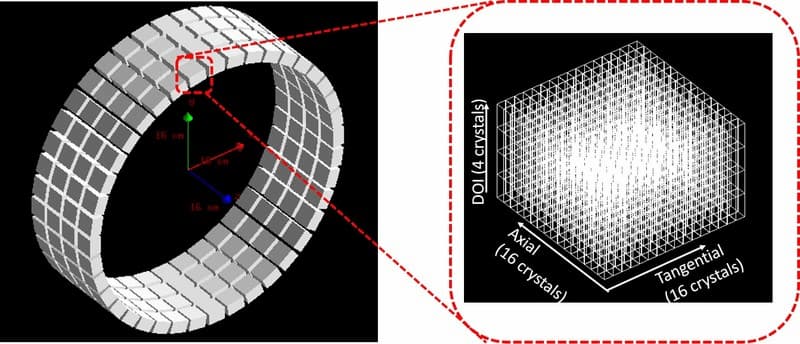
In the doiPET example, a positron emission tomography (PET) scanner with depth-of-interaction detectors is presented (Fig. 1). Usually, in a real PET system, position-sensitive detectors composed of a scintillator array and photomultiplier tubes (PMTs) are used. In addition to the tangential and axial plane, the interacting points between a scintillator and gamma-rays in the DOI (depth of interaction) direction can be identified by a variety of techniques. Many DOI methods have been proposed based on pulse-shape discrimination, reflector control of the optical photons, dual-end readout, and radial voxel segmentation. In this example, the effect of reflector insertion on the position response of the PMT is considered.
Data scoring procedures in the simulation
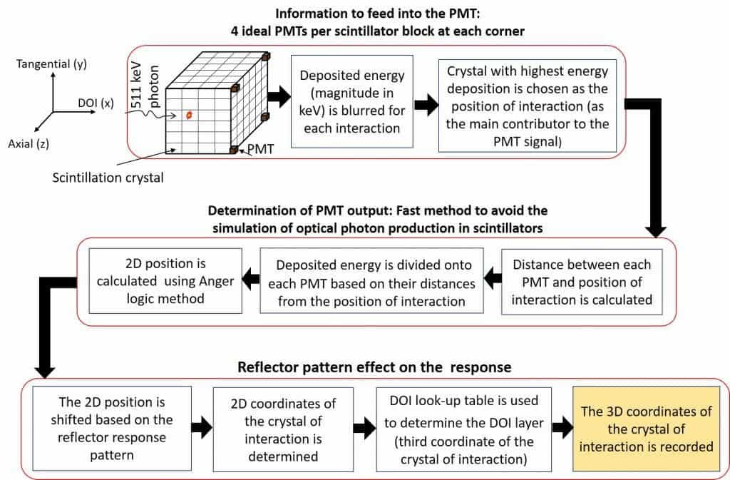
We emulate the identification of the DOI layer by assuming a reflector pattern and four ideal photomultiplier tubes (PMTs) placed at each corner of the crystal block. Here, we should note that the reflectors and PMTs are NOT physically placed in the simulation, and the optical photons are not simulated as it takes a very long time. Rather, the effect of the reflectors on the position response of the PMTs is modelled according to the reflector pattern. The method by which Anger logic is applied and the mechanism by which the crystal is identified in 3D is given in the flow chart shown in Fig. 2.
Reflector pattern and shifting the 2D coordinates
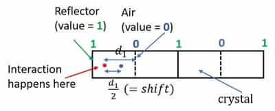
The pattern of the reflector between crystals is identified as having values 1 and 0 (see Fig. 3) such that:
- value = 1 when the reflector exists between two adjacent crystals
- value = 0 when the reflector does not exists between two adjacent crystals
For each interaction, a shift is assumed to be half the distance from the point of interaction to the air gap. Therefore, the shift in the position response in Fig. 3 is d1/2 (equation 1).
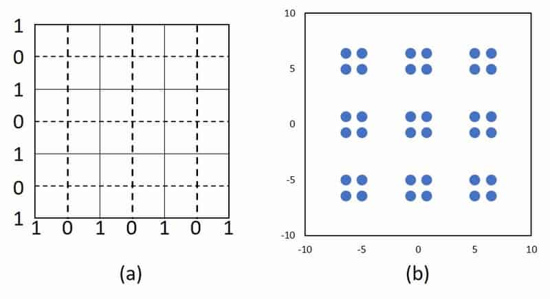
In the following example, consider a crystal arrangement with 6 × 6 × 1 (tangential × axial × DOI) crystal array. We assume the interaction has occurred at the center of each crystal. Therefore, based on the reflector pattern placed between adjacent crystals (Fig. 4 (a)) and eq. (1), the resulting position response is shown in Fig. 4 (b).
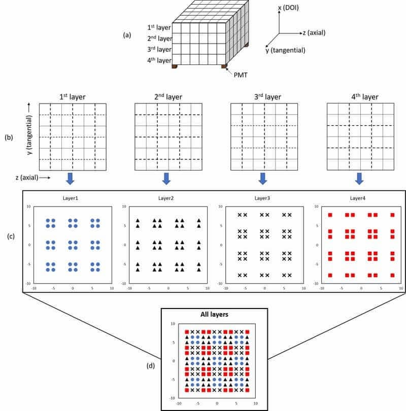
Reflector pattern in 4-layer DOI detector
Fig. 5 (a) shows the conceptual scheme of the 4-layer DOI detector coupled with four ideal PMTs. The reflector patterns for each layer are shown in Fig. 5 (b), and the expected response for each layer is shown in Fig. 5 (c). The overall position response when projected in 2D position histogram is also shown in Fig. 5 (d).
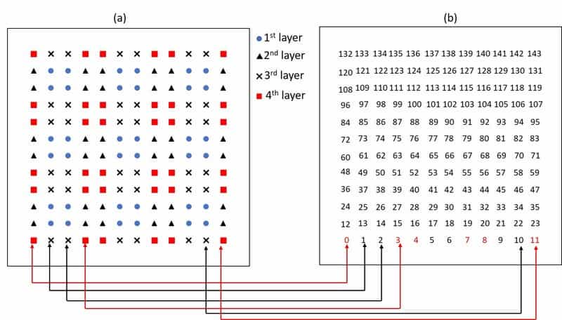
Position interaction in 2D position histogram and DOI look-up table
A DOI look-up-table is prepared by mapping the 2D position histogram map (Fig. 6 (a)) and the crystal ID map (Fig. 6 (b)). For example, all the position responses that are at (or near) the red rectangular positions are identified as layer 4. Thus, crystal with IDs of 0, 3, 4, 7, 8, 11, 36, … etc are crystals at layer 4.
Crystal dependent energy resolution
In a real PET system, there are variations in the energy resolution of the crystals. This variation in energy resolution depends on the number of observed scintillation photons, anode uniformity (variance of anode gains in the photomultiplier tube) and electrical noise. Other factors include the variation in the scintillation light collection and the scintillation light attenuation in the scintillator. Therefore, each crystal in each block will have different energy resolution. To model this inter-crystal variation, a Gaussian model of crystal-dependent energy resolution at FWHM is assigned for each crystal in each block, and an option to choose crystal-dependent or fixed energy resolution is provided in the doiPET example.
References
[1] Y. Hirano et al., “Performance evaluation of a depth-of-interaction detector by use of position-sensitive PMT with a super-bialkali photocathode” Radiol. Phys. Technol., 7:57–66, 2014.
[2] T. Tsuda et al., “A four-layer depth of interaction detector block for small animal PET” IEEE Trans Nucl Sci. 51:2537–42, 2004
[3] E. Yoshida et al., “Development of a Whole-Body Dual Ring OpenPET for in-Beam PET”, IEEE Trans. Rad. Plas.Med Sci., 1:293-300, 2017
Last updated: 05/02/2022 by S. Guatelli