Advanced Example gammaray_telescope
Responsible Geant4 Collaborator: Francesco Longo (INFN-Ts, Trieste, Italy)
Developers: F. Longo (Ferrara), R. Giannitrapani (Udine) & G. Santin (Trieste) – December 2000. Acknowledgments to the Geant4 Collaboration, and, in particular to R. Nartallo, A. Pfeiffer, M. G. Pia and G. Cosmo
Short description
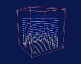
GammaRayTel is an example of application of Geant4 in a space environment. It simulates a typical telescope for gamma ray analysis; the detector setup is composed by a tracker made with silicon planes, subdivided in ladders and strips, a CsI calorimeter and an anticoincidence system. In this version, only the tracker is sensitive; the hits on the tracker strips are registered and relevant information (energy deposition, position etc) are dumped to an external ASCII file for subsequent analysis. The main features of this example are:
- Macros for the visualization of geometry and tracks with OpenGL, VRML and DAWN drivers
- Implementation of messengers to change some parameters of the detector geometry, the particle generator and the analysis manager (if present) runtime
- Readout geometry mechanism to describe an high number of subdivisions of the planes of the tracker (strips) without affecting in a relevant way the simulation performances
- Histogramming
- User interfaces via Xmotif or normal terminal provided
Setting up the environment variables. The reader should refer to the README file of the example.
Detector description. The detector is defined in GammaRayTelDetectorConstruction.cc. It is composed of a Payload with three main detectors, a Tracker (TKR), a Calorimeter (CAL) and an Anticoincidence system (ACD). The standard configuration is made of a TKR of 15 Layers of Si detectors, with Lead converter, and a CAL of 8 layers of CsI. Four lateral panels and a top layer of plastic scintillator (ACT and ACL) complete the configuration. The Si detectors are composed of two silicon planes subdivided in strips aligned along the X axis in one plane and along the Y axis for the other. It is possible to modify in some way this configuration using the commands defined in GammaRayTelDetectorMessenger. This feature is available in the UI through the commands subtree “/payload/” (see the help command in the UI for more information).
Physics processes. This example uses the standard Electromagnetic processes.
Particle Generator. The GammaRayTelParticleGenerationAction and its Messenger let the user define the incident flux of particles, from a specific direction or from an isotropic background. The user can define also between two spectral options: monochromatic or with a power-law dependence. The particle generator parameters are accessible through the UI tree “/gun/” (use the UI help for more information). We are planning to include, in the next release of this example, the new General Particle Source module of G4.
Hit. In this version only the hits from the TKR are recorded. Each hit contains the following information:
- ID of the event (this is important for multiple events run)
- Energy deposition of the particle in the strip (keV)
- Number of the strip
- Number of the plane
- Type of the plane (1=X 0=Y)
- Position of the hit (x,y,z) in the reference frame of the payload
- The hit information are saved on an ASCII file named Tracks_N.dat, where N is the progressive ID number associated to the run.
Histogramming. Some hits information can be visualized runtime using Lizard (if it is available on the user platform); two 2D histograms and two 1D histograms can be visualized and saved (as PostScript files) during the simulation run. The 2D histograms contain the hits positions on the TKR projected on the XZ plane and the YZ plane; the 1D histograms contain the energy deposition in the last X plane of the TKR and the hits distribution along the X planes of the TKR (note that this histograms have been chosen more for pedagogical motivation than for physical one). These histograms are filled and updated at every event and are initialized with each new run; the scale of the histograms is automatically derived from the detector geometry.
Through a messenger it is possible to set some options with the UI subtree “/analysis/” (use the UI help for more info); in particular it is possible to enable or disable the drawing of the 1D and 2D histograms at every event and to enable or disable the saving of PostScript files at the end of each run. If you feel that the simulation is too slow with the histograms updated every event, you can disable the drawing and retain the saving. Please note that the updating of the histograms is triggered only when there is some hit in an event. In this example we only show the use of very basic feature of this new simulation/analysis framework.
Classes Overview. This is the overview of the classes defined in this example:
- GammaRayTelPrimaryGeneratorAction: User action for primaries generator
- GammaRayTelPrimaryGeneratorMessenger: Messenger for interactive particle generator parameters modification via the User Interface
- GammaRayTelPhysicsList: Determination of particles and processes active in this example
- GammaRayTelDetectorConstruction: Geometry and material definitions for the detector
- GammaRayTelDetectorMessenger: Messenger for interactive geometry parameters modification via the User Interface
- GammaRayTelAnalysis: Analysis manager class
- GammaRayTelAnalysisMessenger: Messenger for interactive analysis options modification via the User Interface
- GammaRayTelRunAction: User run action class
- GammaRayTelEventAction: User event action class
- GammaRayTelAnticoincidenceHit: Description of the hits in the anticoincidence system (ACD)
- GammaRayTelCalorimeterHit: Description of the hits in the calorimeter (CAL)
- GammaRayTelTrackerHit: Description of the hits in the tracker (TRK)
- GammaRayTelAnticoincidenceSD: Description of the sensitive detector associated with the anticoincidence system (ACD)
- GammaRayTelCalorimeterSD: Description of the sensitive detector associated with the calorimeter system (CAL)
- GammaRayTelTrackerSD: Description of the sensitive detector associated with the calorimeter system (TRK)
Last updated: 01/12/2023 by S. Guatelli