Advanced Example nanobeam
Responsible Geant4 Collaborator and Developer: Sebastien Incerti, LP2i, IN2P3, Bordeaux, France
Short description
The nanobeam example simulates the beam optics of the nanobeam line installed on the AIFIRA electrostatic accelerator facility located at LP2i, Bordeaux-Gradignan, France. For more information on this facility, please visit: http://www.cenbg.in2p3.fr/.
The code explains how to use Geant4 in order to calculate:
- intrinsic aberration coefficients of the nanobeam line,
- beam images from a realistic primary emittance distribution,
- grid shadow images.
For more information on this irradiation facility, please visit: https://www.lp2ib.in2p3.fr/.
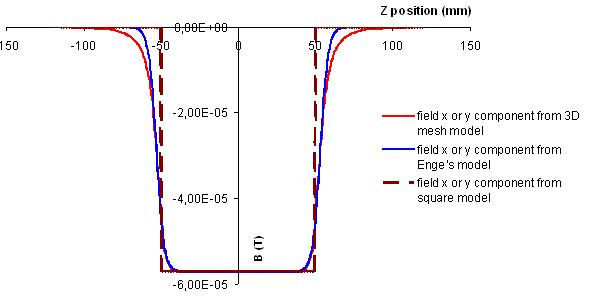
Three quadrupole field models can be used in this advanced example:
- a simple square field model,
- a 3D mesh field model computed from OPERA3D,
- an analytical model based on Enge’s model.
Simulated experimental setup
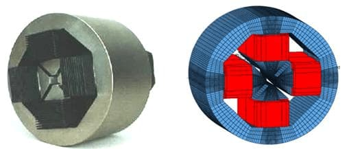
The nanobeam line consists of a long working distance doublet-triplet of focusing quadrupole magnets (Oxford Microbeams Ltd. OM50), with an intermediate focus point. The full magnetic configuration of the nanobeam line is simulated. A full description of the simulated setup is described in our publications (see bottom of this page).
Physics
The example runs with protons with fluctuating energies around 3 MeV. Standard electromagnetic processes are activated by default.
How to install and run the example
Several macro files are provided. They are located in the macros directory:
- for the computation of intrinsic aberration coefficients:
- coef-square.mac : using square magnetic field model (=default.mac)
- coef-map.mac : using 3D map magnetic field model
- coef-enge.mac : using Enge’s analytical field model
- for the simulation of the beam image with a realistic emittance:
- image-square.mac : using square magnetic field model
- image-map.mac : using 3D map magnetic field model
- image-enge.mac : using Enge’s analytical field model
- for the simulation of grid shadow images:
- grid-square.mac : using square magnetic field model
- grid-map.mac : using 3D map magnetic field model
- grid-enge.mac : using Enge’s analytical field model
Please, look at the README file provided with the example for more details.
Simulation results
The output consists in a ROOT file. These files can be easily analyzed using the provided ROOT macro file plot.C. This macro file shows:
- the beam profile along the nanobeam line (only for the computation of intrinsic coefficients),
- the beam image (Y vs X) on target,
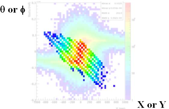
- the beam emittance (THETA vs X) and (PHY vs Y) on target,
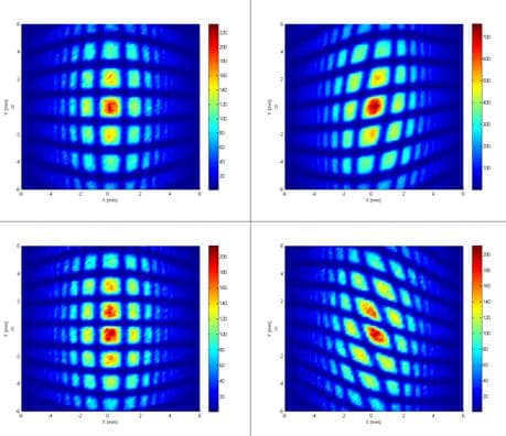
- and the grid shadow image.
For more details, please refer to the README file provided with the example. The ROOT website is available at:http://root.cern.ch.
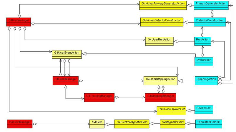
Code design
The Nanobeam code design obtained from the Rational Rose software is shown below. Manager classes are filled with red and Nanobeam classes are filled with sky blue.
Suggested papers
- Technical description of the CENBG nanobeam line, Ph. Barberet, S. Incerti,, F. Andersson, F. Delalee, L. Serani, Ph. Moretto, Nucl. Instrum. and Meth. B (2009) link
- A detailed ray-tracing simulation of the high resolution microbeam at the AIFIRA facility, F. Andersson, Ph. Barberet , S. Incerti, Ph. Moretto , H. Seznec , M. Simon, Nucl. Instrum. and Meth. B 266 (2008) 1653-1658 link
- Monte Carlo simulation of the CENBG microbeam and nanobeam lines with the Geant4 toolkit, S. Incerti, Q. Zhang, F. Andersson, Ph. Moretto, G. W. Grime, M. J. Merchant, D. T. Nguyen, C. Habchi, T. Pouthier, H. Seznec, Nucl. Instrum. and Meth. B 260 (2007) 20-27 link
- Geant4 simulation of the new CENBG micro and nanoprobes facility, S. Incerti, C. Habchi, Ph. Moretto, J. Olivier and H. Seznec, Nucl. Instrum. and Meth. B 249 (2006) 738-742 link
- A comparison of ray-tracing software for the design of quadrupole microbeam systems, S. Incerti, R.W. Smith, M. Merchant, G.W. Grime, F. Méot, L. Serani, Ph. Moretto, C. Touzeau, Ph. Barberet, C. Habchi and D.T. Nguyen, Nucl. Instrum. and Meth. B 231 (2005) 76-85 link
Last updated: 18/02/2022 by S. Guatelli